Shaft layout
| Values | |
|---|---|
| SD / SW | see dimensions pages |
| SH | CH + 1180 mm (1 m/s) |
| SH red. | CH + 400 mm (1 m/s) |
| SP | min. 1000 mm (1 m/s) |
| SP red. | min. 450 mm (1 m/s) |
| TH | max. 40 m/min. 2900 mm (1 m/s) |
| max. 75 m (>1 m/s) | |
| HST | min. DH+450 mm / max. 11 m |
| HST2 | min. 250 mm |
| CH | 2100 / 2200 / 2300 mm |
| DH | 2000 / 2100 mm |
| DW | 700 – 1000 mm |
| Key | |
|---|---|
| SD | shaft depth |
| SW | shaft width |
| SH | shaft head |
| SP | shaft pit |
| TH | travel height |
| HST2 | min. height between floors |
| CH | cabin height |
| DH | door height |
| FFL | finished floor level |
| UFL | unfinished floor level |
Note: All shaft dimensions with standard tolerances. The values shown correspond to a generic installation under ideal circumstances. During the planning phase, all applicable regulations stipulated by relevant notified bodies and all applicable national regulations should be considered. All cabins with integrated sling.
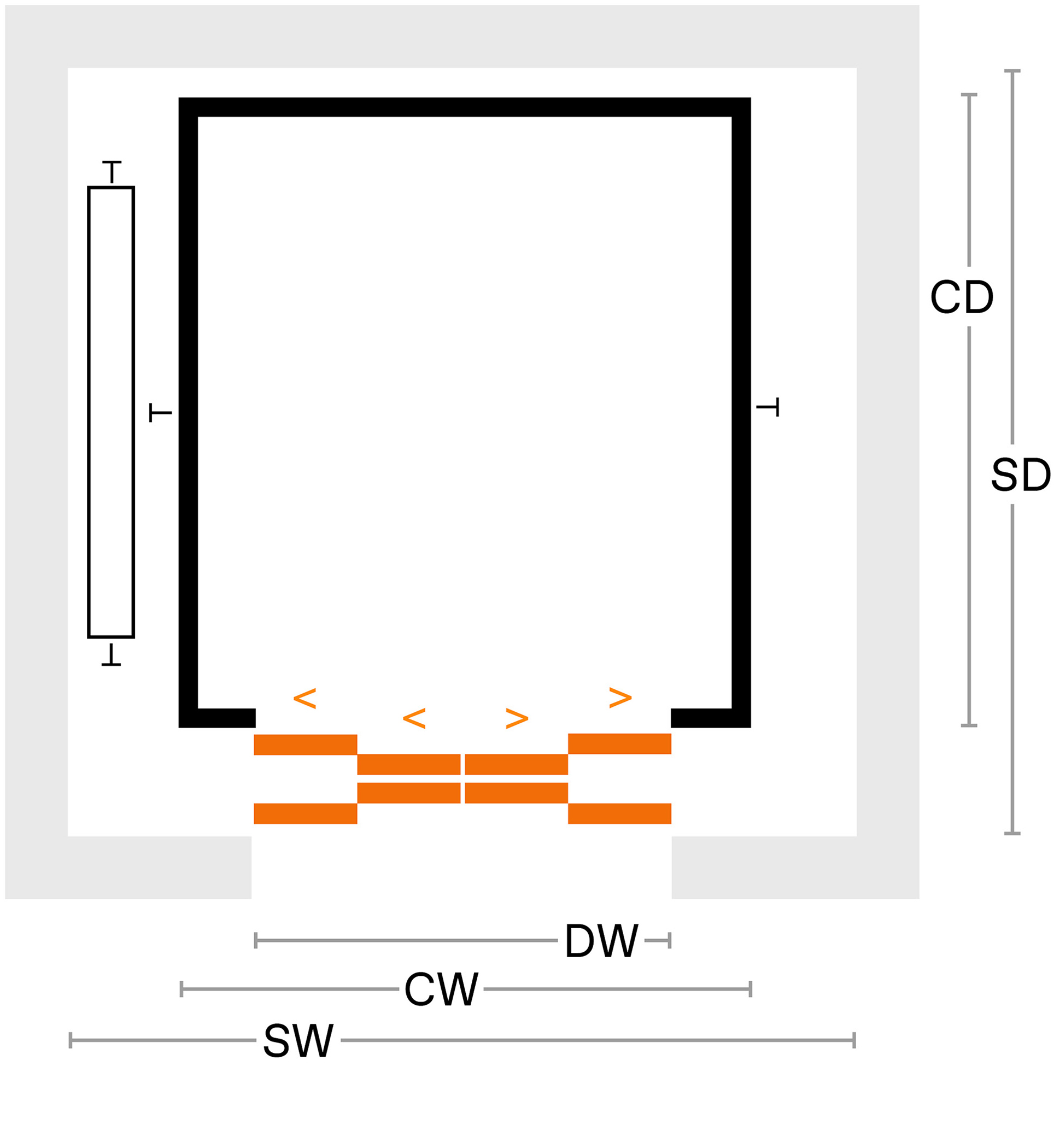
Doors
Doors
| Key | |
|---|---|
| L2 | side-opening door with two door panels |
| L3 | side-opening door with three door panels |
| C4 | central-opening door with four door panels |
| S | single entrance |
| D | double entrance |
| SD | shaft depth |
| CD | cabin depth |
| SW | shaft width |
| CW | cabin width |
| DW | door width |
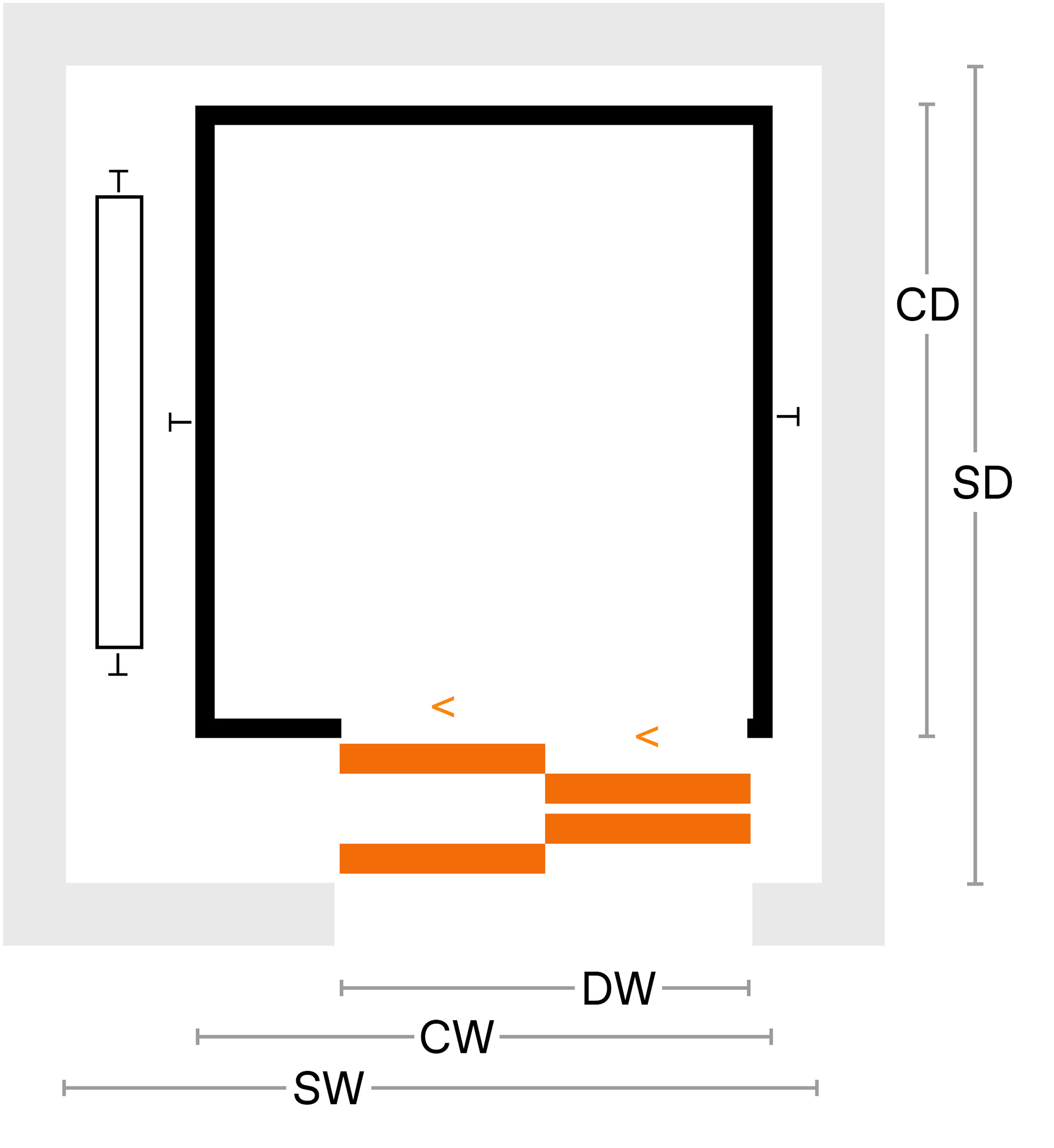
L2 / S
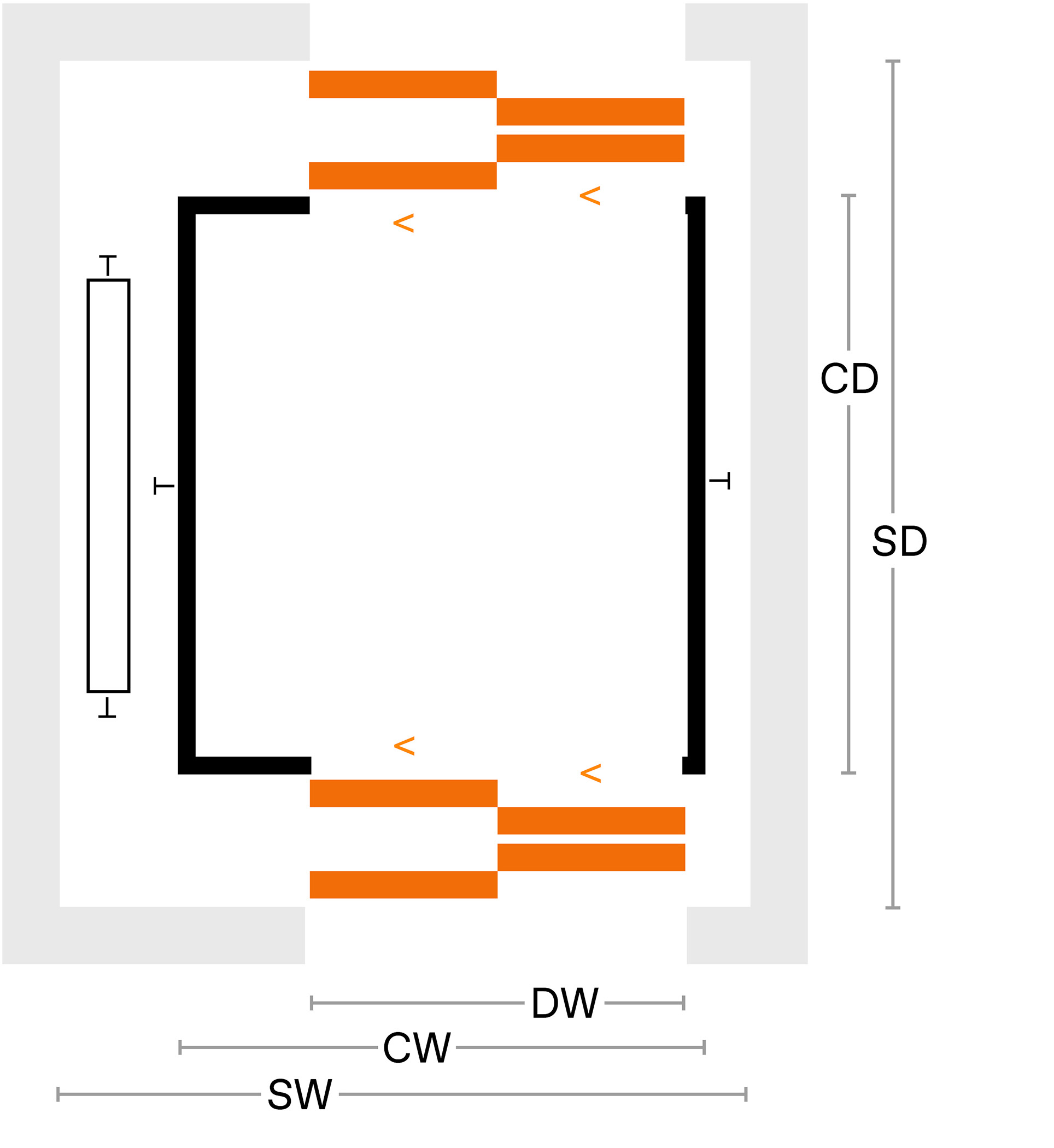
L2 / D
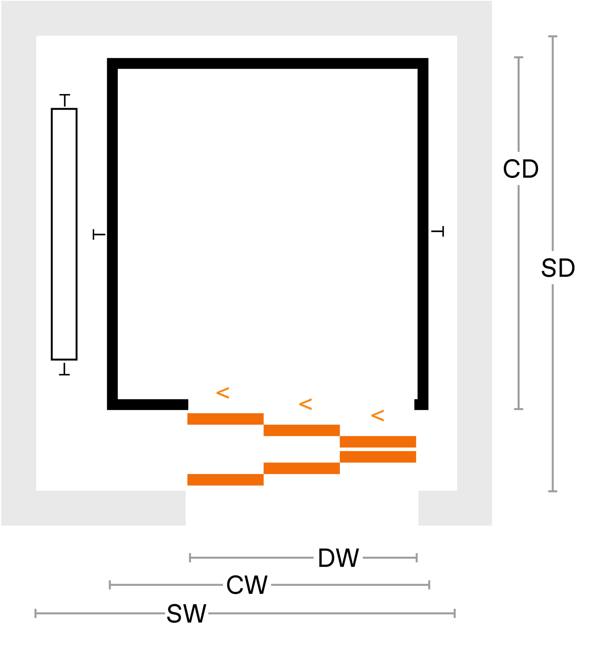
L3 / S